|
| Pearson 10M Electric Drive Unit |
|
|
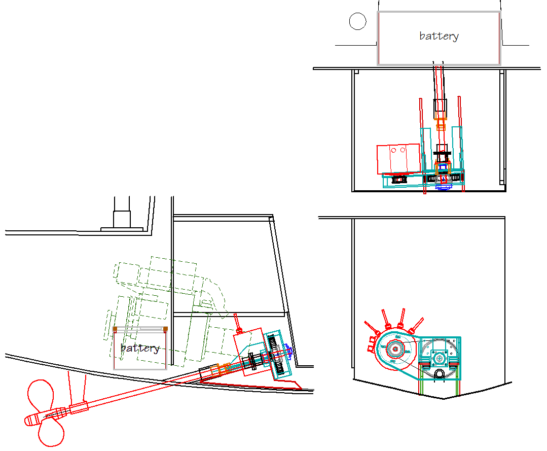
System Description
I'll describe the parts of the drive system starting at the prop and working to the motor. |
|
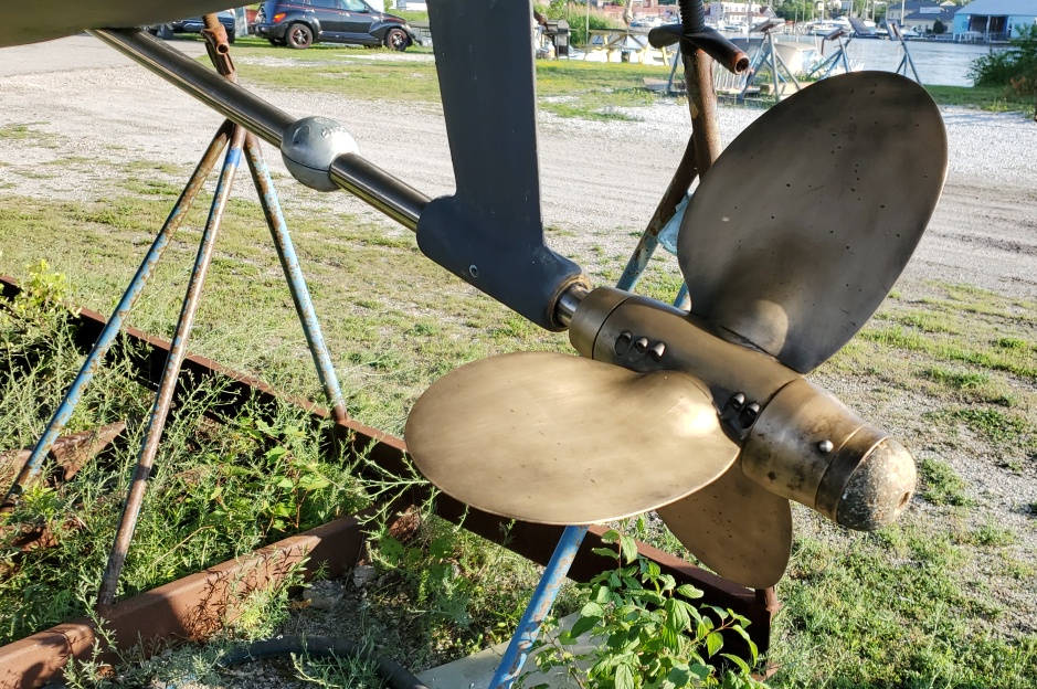
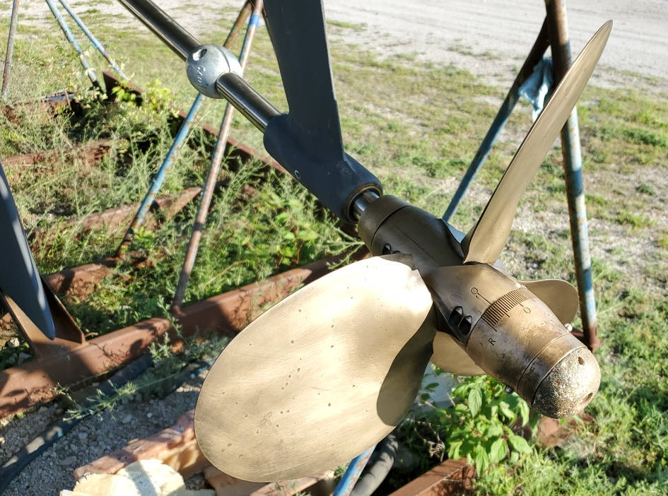
JProp Feathering Propeller
|
|
Prop Shaft and Stuffing Box
Next is the prop shaft. The boat has a conventional prop shaft riding in a standard cutlass bearing in a strut and a standard stuffing box with GFO Gortex packing. Same setup as the diesel. The shaft is 1-1/8 diameter Auquiment 19 stainless steel. I got it when I installed the propeller in 2002. |
|
Couplers
|
|
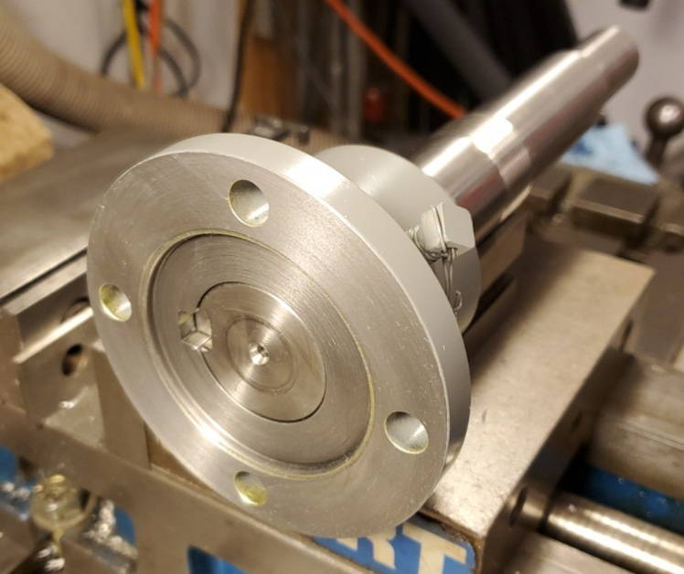
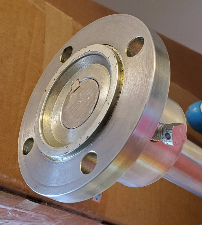
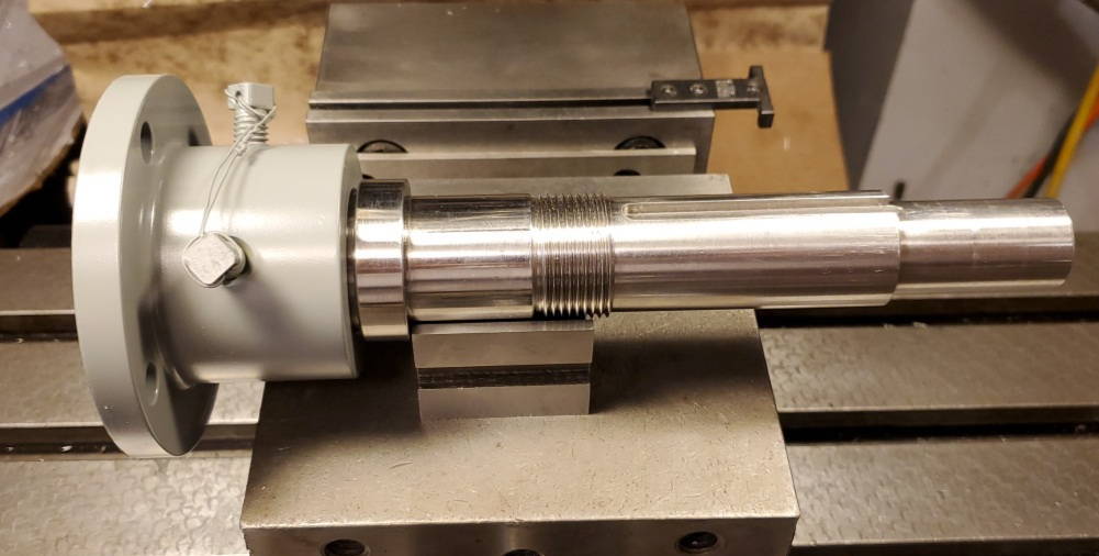
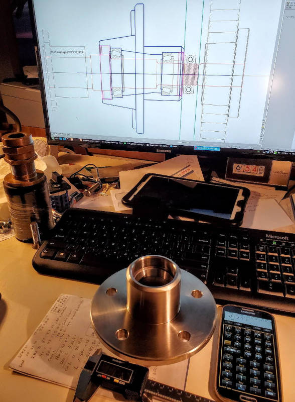
Output Shaft
There is a photo here of the bare shaft, and the shaft with the output coupler installed. |
|
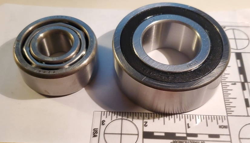
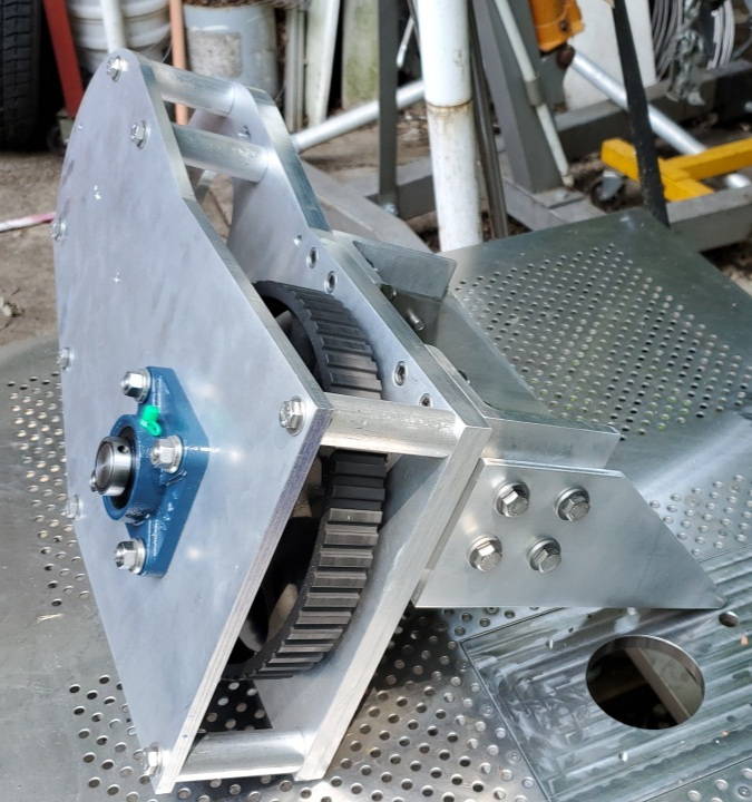
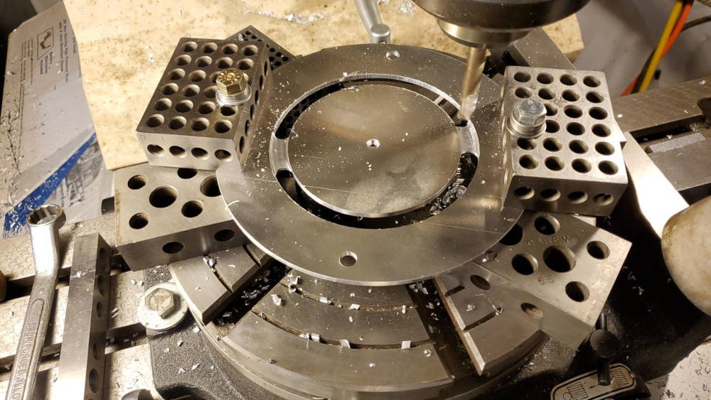
Thrust Bearing
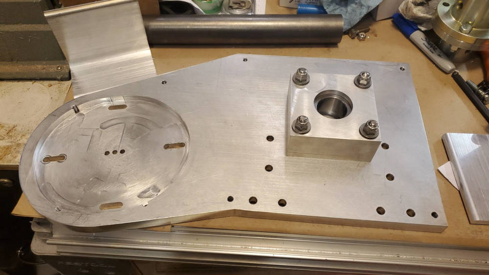
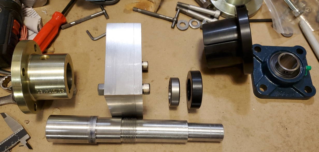
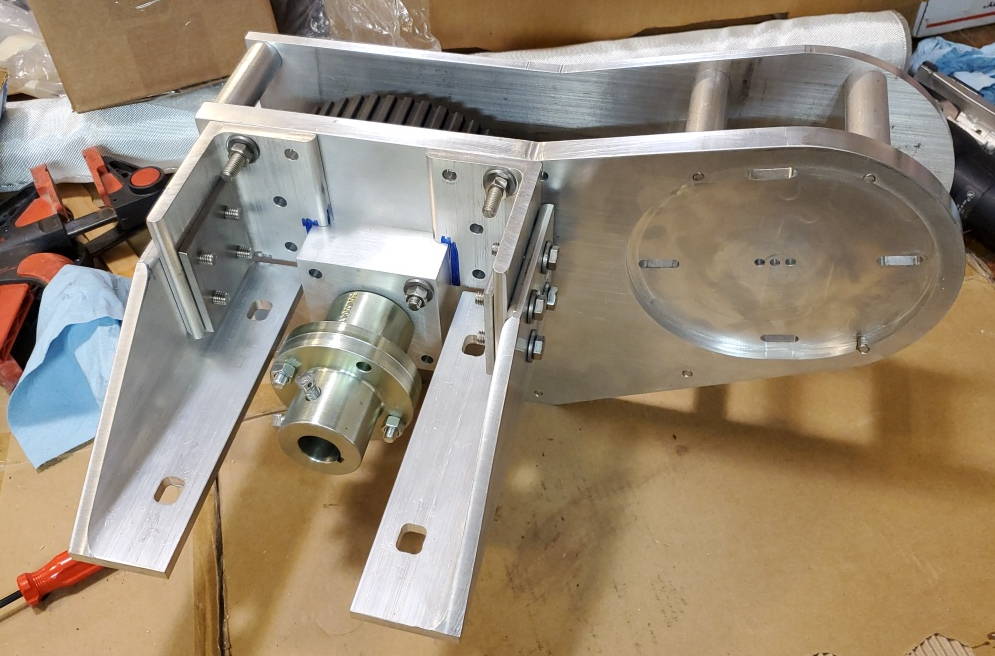
I looked at what was used for a thrust bearing in the Walter V-drive that came with the boat. It uses a double roller angular contact ball bearing (type 5304). The v-drive is rated for about 50HP at 2500 rpm. I found the same bearing but several sizes larger with rubber seals (5207-2RS). This would easily be strong enough and would not require an oil bath or any additional seals. And they are not very expensive. I made an aluminum housing with a slip fit for the bearing. The housing bolts to the back of the motor mounting plate. The bearing is rated for 6000 lbs and 7000RPM so I am operating well within its performance envelope (thrust load for a 25HP diesel is on the order of 500-800 lbs - reference?). I ran the motor for about 100 hrs in the first season with no signs of wear on the bearing. First photo of Walter V-drive thrust bearing (left) and the 5207-2RS bearing (right) I used in the drive unit. Second photo is the thrust bearing housing I fabricated from aluminum. |
|
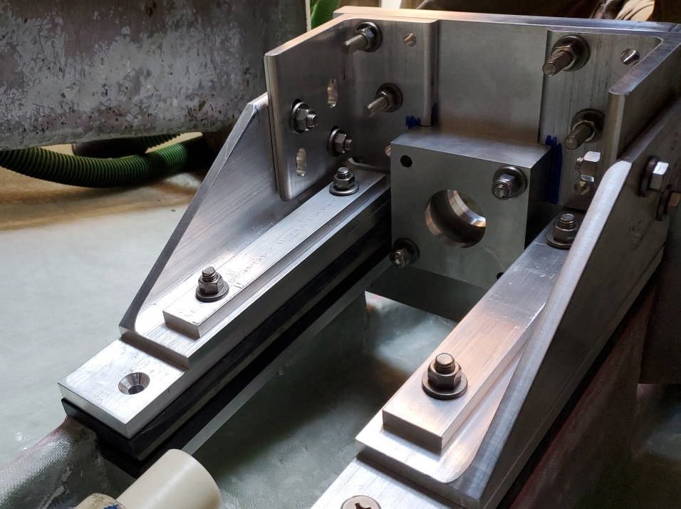
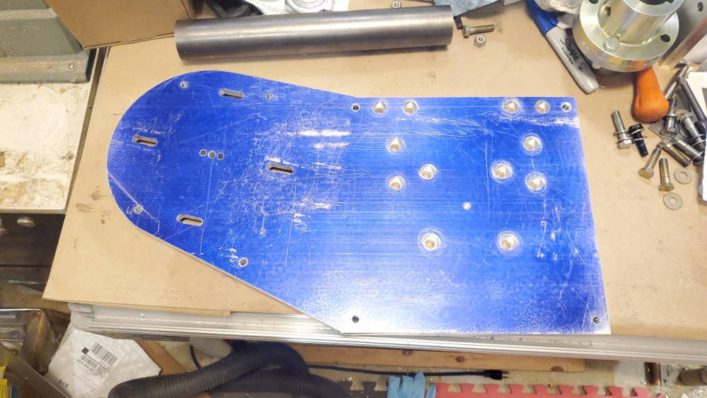
Motor Mounting Plate
|
|
Threaded Collar and Bushing on Output Shaft
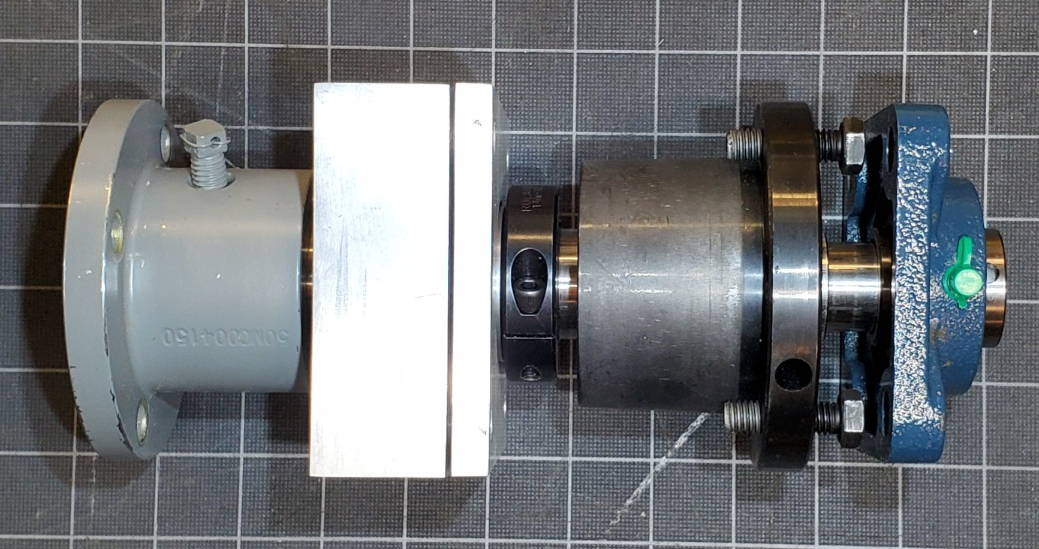
There's a photo here of these parts without the thrust bearing housing to show how they fit together. |
|
Drive Pulley Bushing
Forward of the locking collar is the drive pulley bushing. The large drive pulley fits onto this bushing which in turn clamps it to the output shaft. The toothed belt drive pulley fits onto this bushing. There's a photo here of these parts without the thrust bearing housing to show how they fit together. |
|
Front Cover and Pilot Bearing
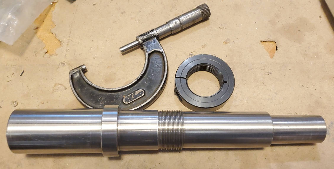
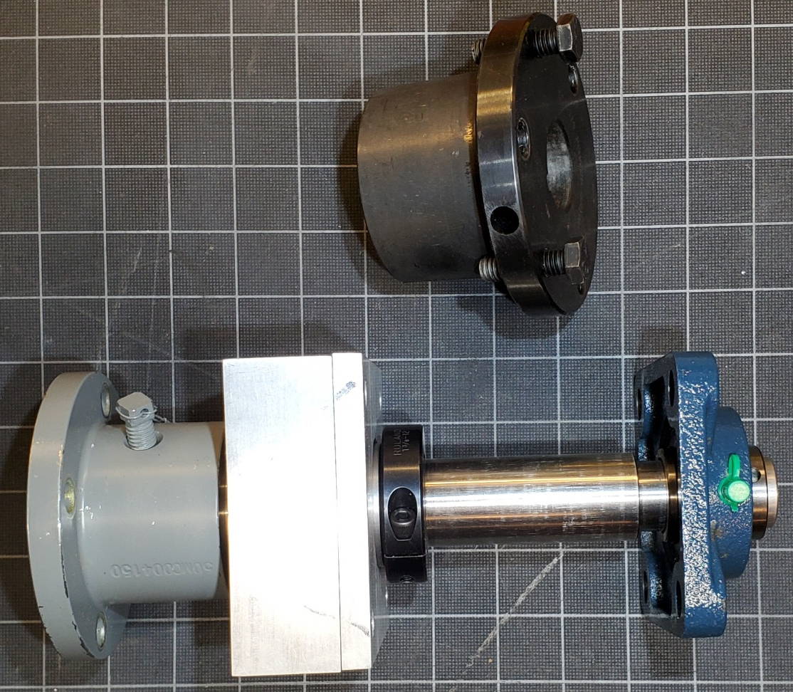
At the forward end the output shaft extends through the front cover (made from 3/8" aluminum) and fits into a pilot bushing mounted to the front cover. The pilot bushing is self aligning and there is some play in the mounting that allows it to be positioned concentric with the shaft. After the drive unit is assembled but before the drive belt is tensioned, the pilot bushing is tightened in place. I wasn't sure this pilot bushing would be needed but after installing it the run-out of the shaft was reduced from .005" to a bit better than .001". The front cover is a 3/8" aluminum plate secured to the mounting plate with long bolts through stand-offs. The cover protects the belt and provides a mounting for the pilot bearing. There's a photo here of shaft with all the parts on it. |
|
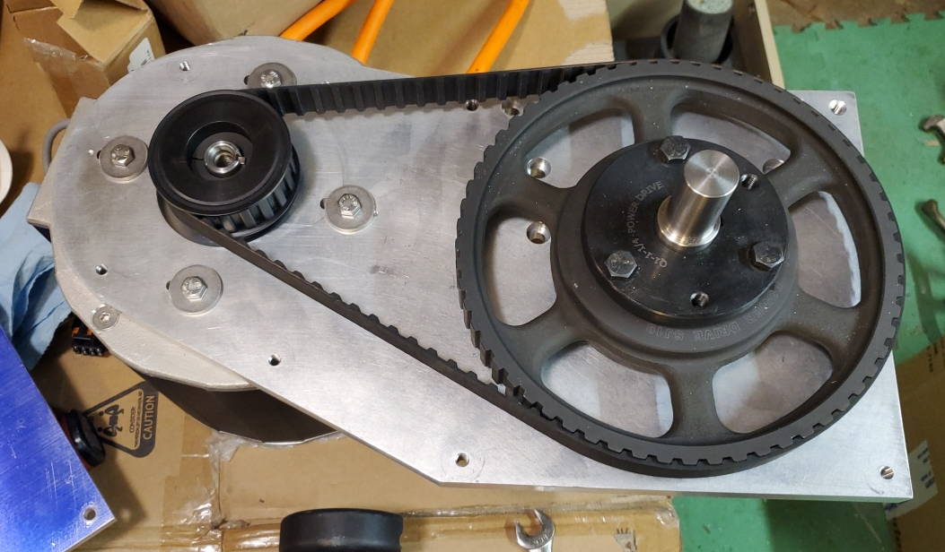
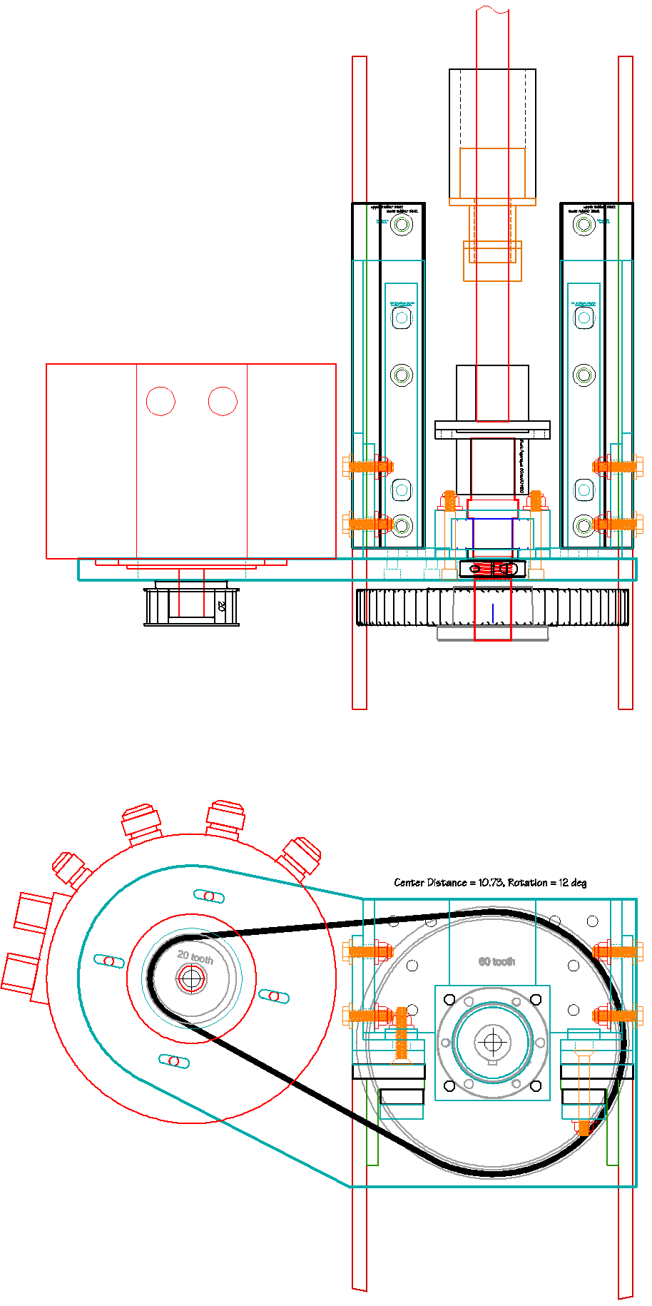
Drive Pulleys and Belt
The drive pulleys mount to the output shaft (on the drive pulley bushing) and on the motor shaft(with another bushing). The drive pulley is 60 teeth, the motor pulley is 20 teeth for a final drive ratio of 3:1. The max motor RPM at 48V is 2400 RPM. The 3:1 reduction gives the prop rotation of 800 RPM. The pulleys and bushings are made of steel and need protection from corrosion just like the parts of an inboard diesel would.
The drive belt is 1" wide type H with a tooth pitch of 1/2". This is a pretty standard belt and pulleys. I sized the belt length using the center-to-center distance between the pulleys (10.73") and the pulley tooth counts (60, 20). There are on-line calculators for this from the belt and pulley manufacturers. |
|
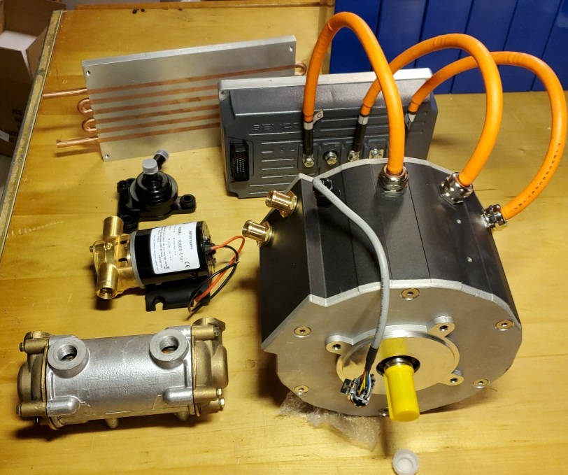
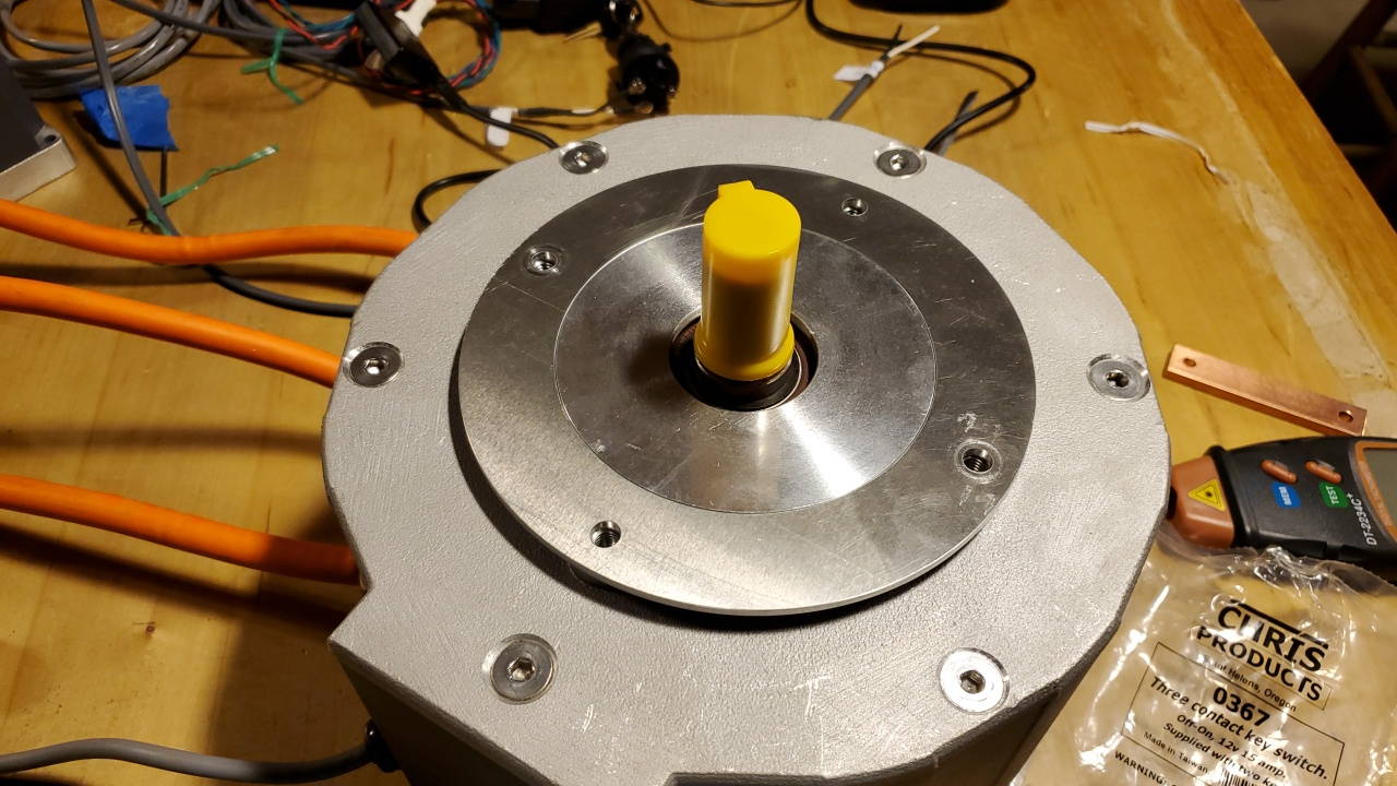
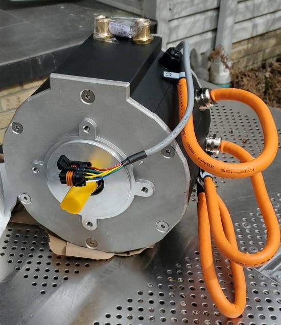
Motor
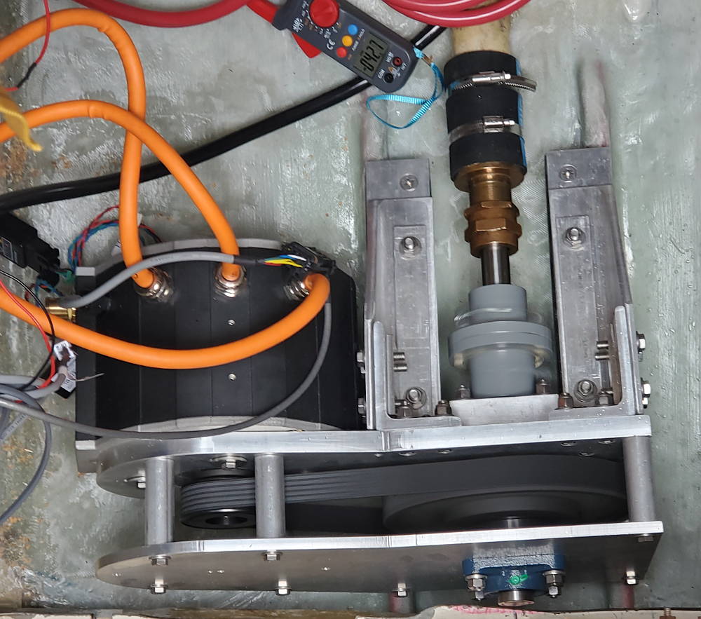
The motor is a Motenergy ME1616. Its 12kW at 48V, water cooled, totally enclosed (IP67), and brushless. It mounts in a recess on the aft face of the mounitng plate to get the motor pulley at the correct height over the front of the plate. I made a spacer for the front face of the motor so it sits flush on the bottom of the recess in the mounting plate. The motor mounting screws fit through slots in the mounting plate so it can slide to tension the belt. The motor weighs about 50lbs. Photos of the face of the motor and the motor with some of the cooling components. |
|
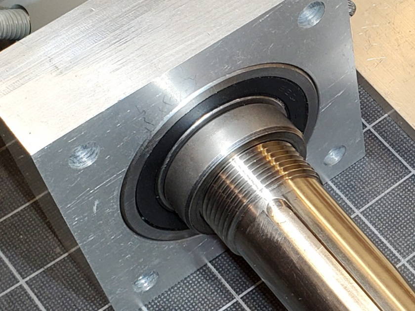
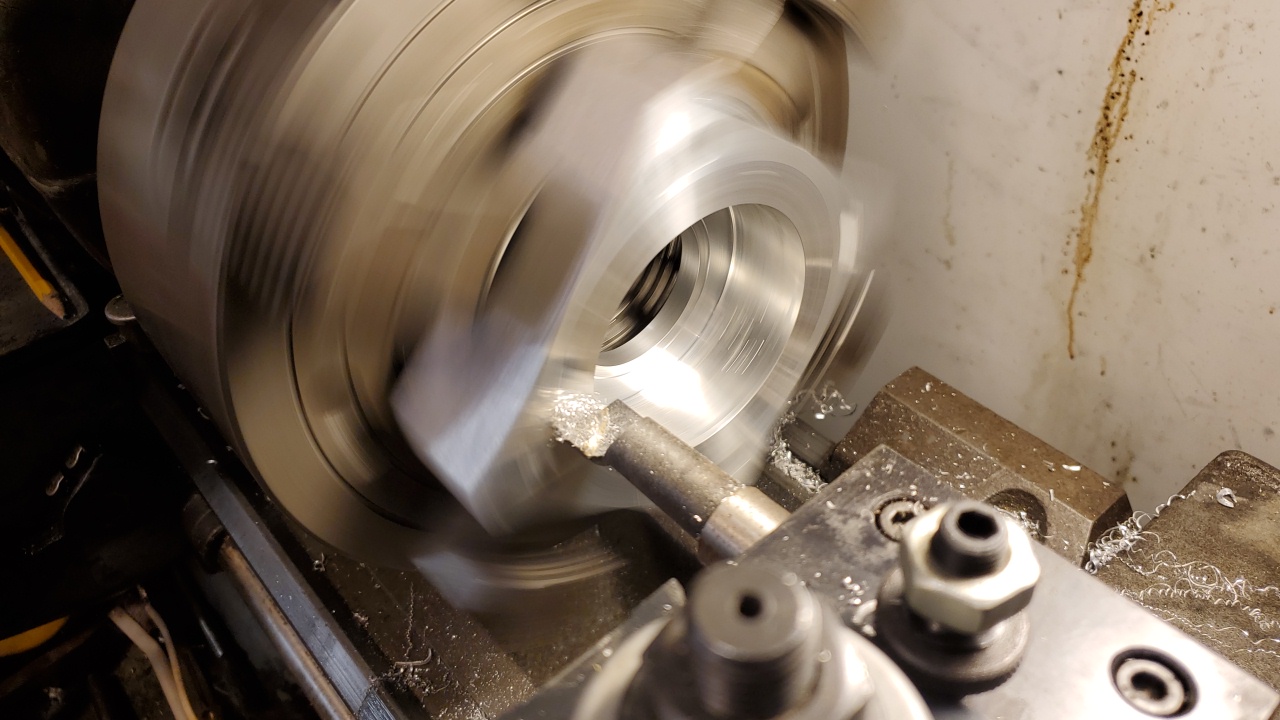
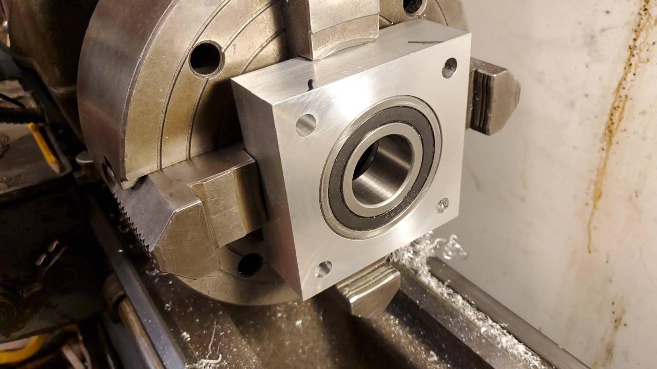
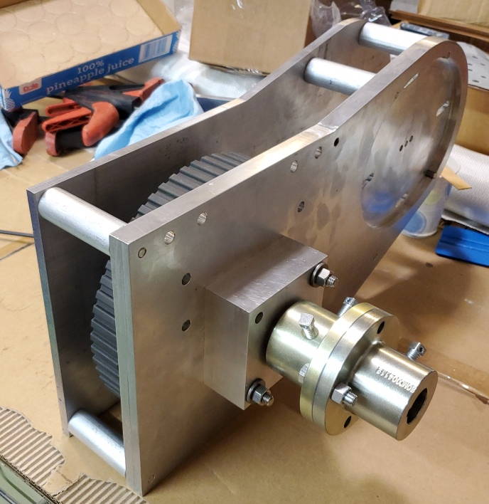
Thrust Bearing Housing
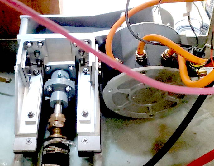
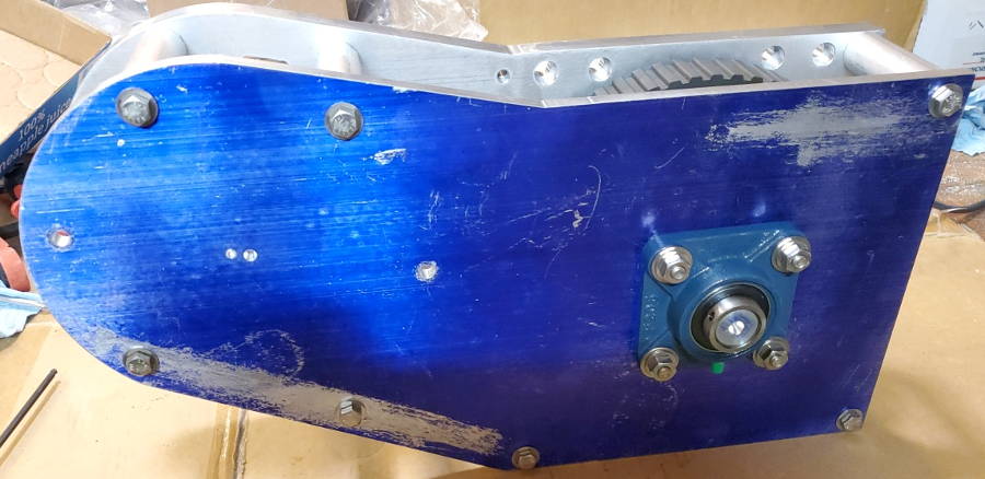
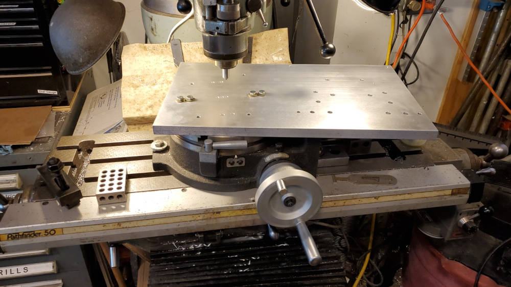
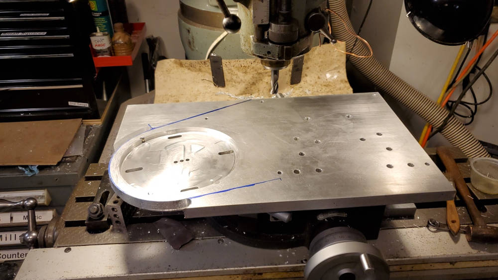
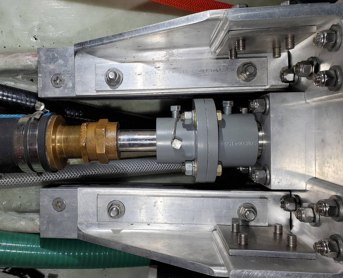
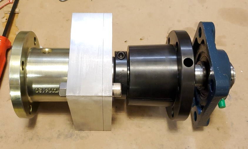
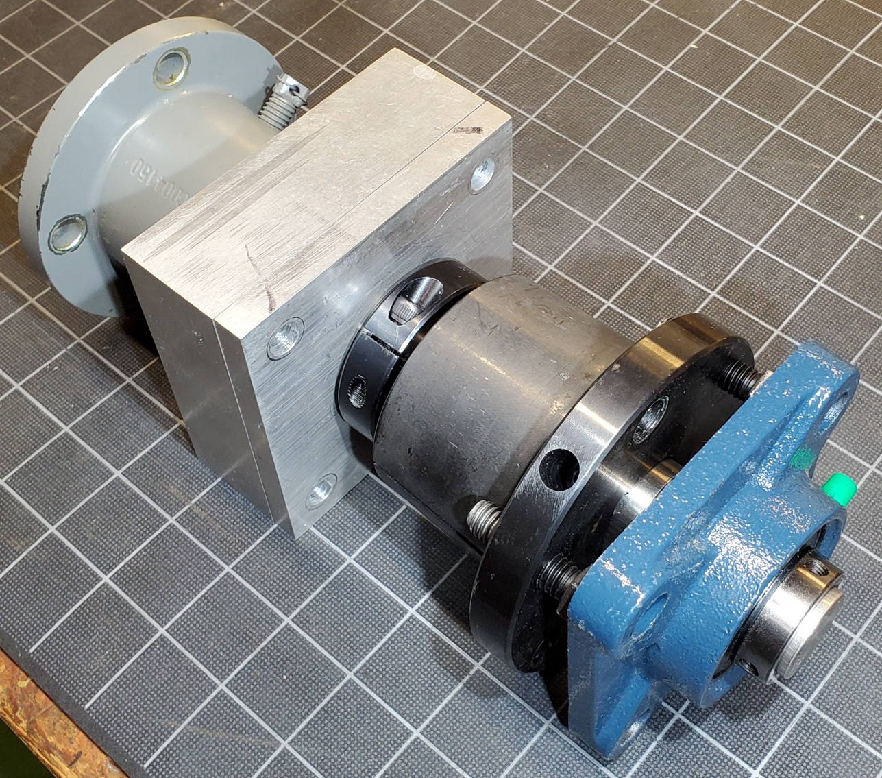
The bearing housing was fabricated from aluminum with operations on the milling machine and the lathe. The bearing is a snug slip fit. The bearing is a 5208-2RS double roller angular contact ball bearing with two rubber seals. It is the same type of bearing used in the original Walter RV-10 V-drive used in the boat but several sizes larger. The bearing is mounted to the shaft between a flange on the aft side and a locking threaded collar on the the forward side.
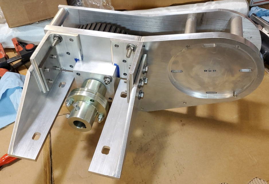
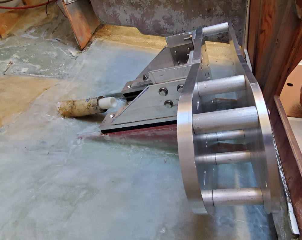
5208-2RS bearing (right) next to the thrust bearing from the original Walter V-drive, thrust bearing in housing attached to back of the drive frame with couplers in place, bearing housing on back of drive unit in place on motor beds.
|
|
Motor face plate, drive belt, and assembled frame Drive Bench Test Videos
|
|
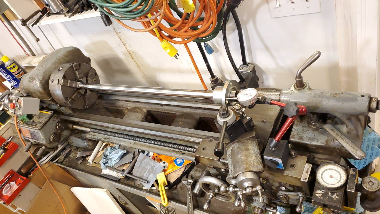
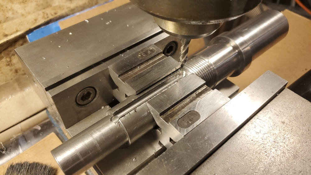
Shaft Details
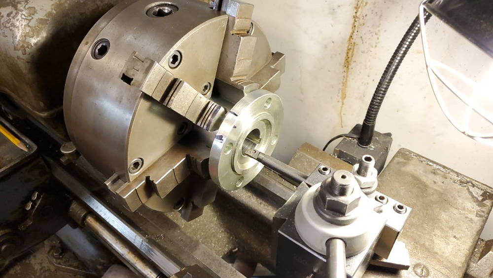
Boring one of the couplers to fit its shaft, facing the prop shaft coupler, and the completed output shaft of the drive unit. The output shaft coupler was machined with a bore to receive the boss on the prop shaft coupler.
|
|
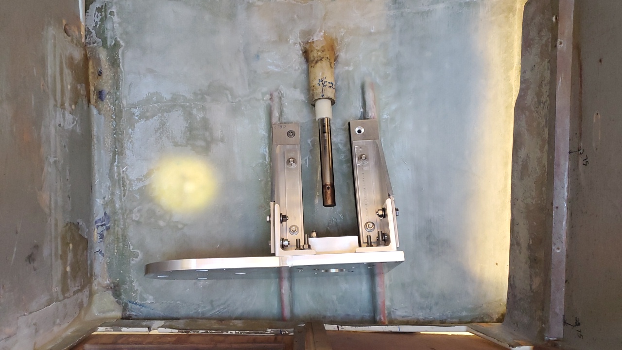
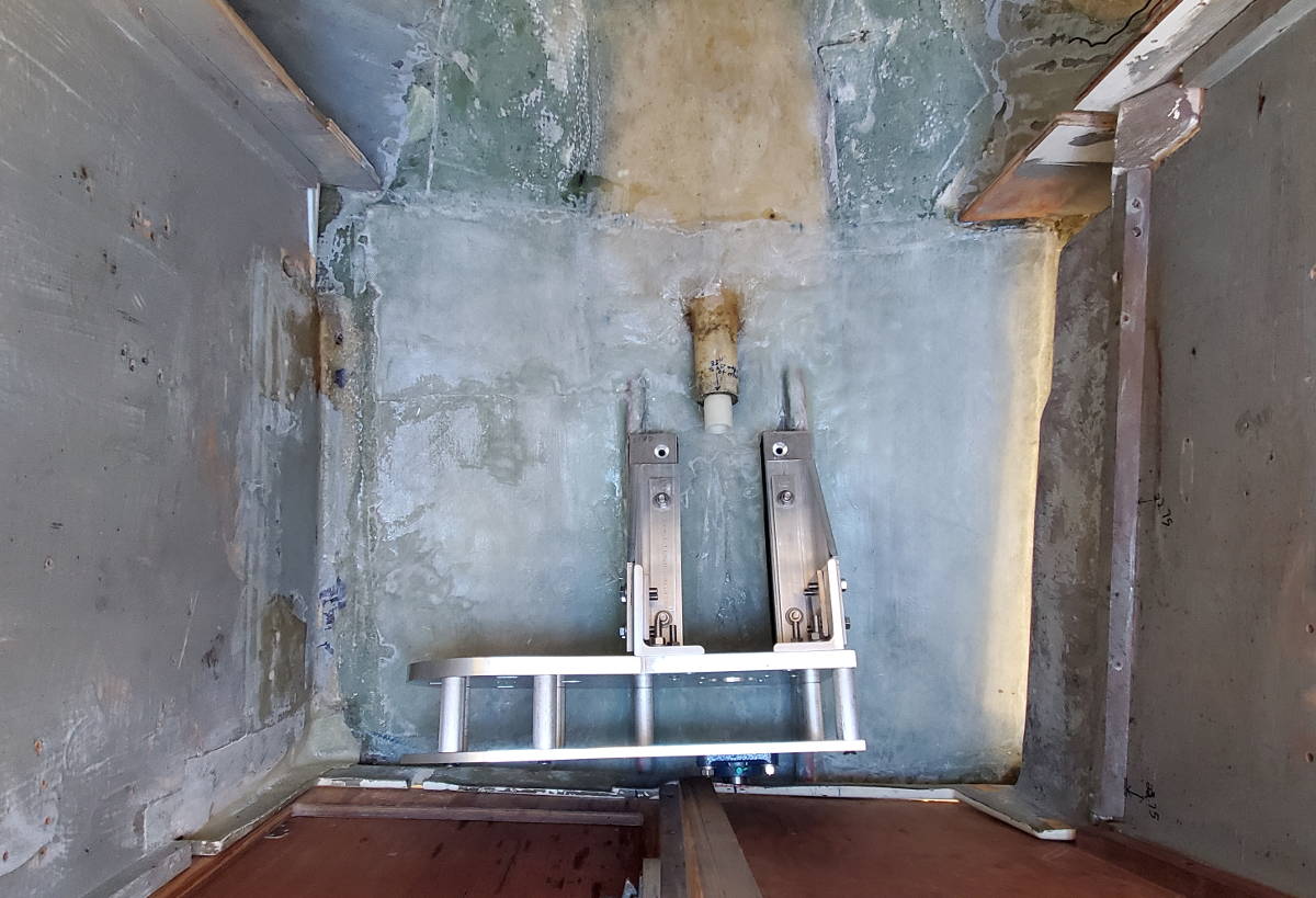
Drive frame test fit on motor beds
|