|
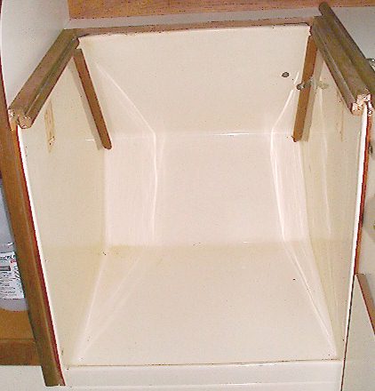
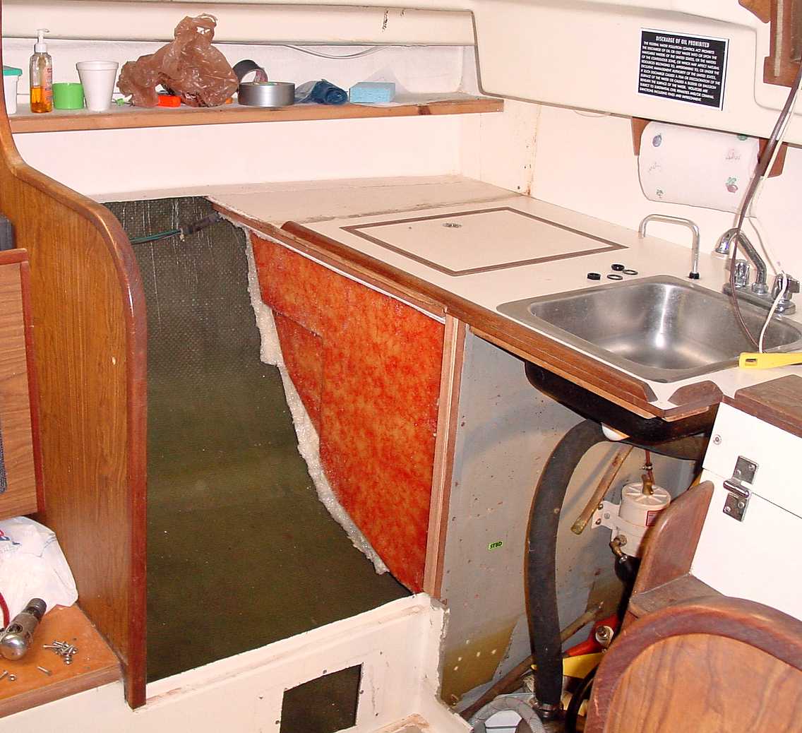
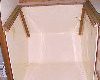
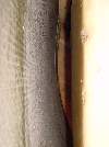
The oven pan (my term) is the fiberglass shell structure in which the oven is hung. It is shaped so that the stove/oven can swing as the boat heels. The
Glasswork was done by chopper gun on a male mold. It is finished on the front with gel coat.
|
|
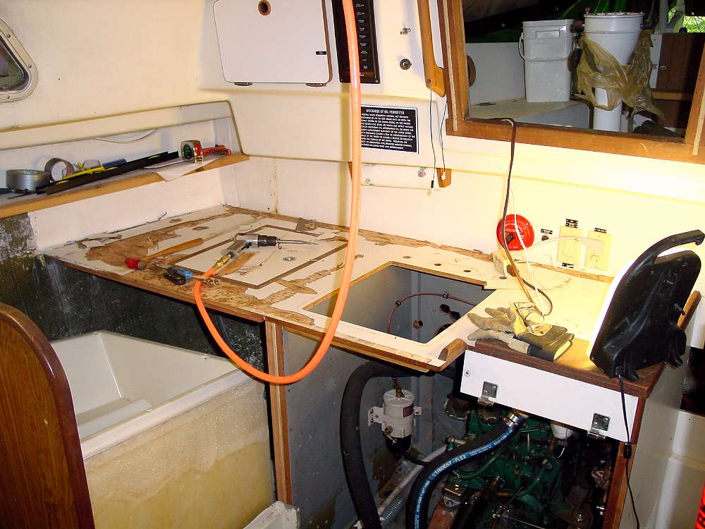
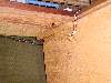
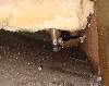
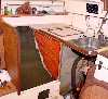
This photo shows the pan with the oven removed. The hole in the upper right is where the copper tube that carried alcohol from the bottle (between 1/4 berth
and engine) to the OEM alcohol stove.
|

|
This is a drawing of the oven pan with measurements. Because of its shape there is a lot of dead space outboard of the pan.
|

|
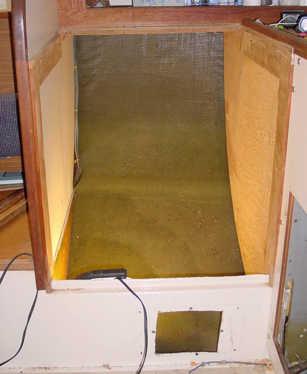
This photo shows the space with the oven pan removed. Removal is a little involved. There are two teak strips that support the stove cover panel. They
need to be removed. That requires removing the bungs in the strips that cover the screws. I cut those out with my Dremel and a carbide bit. It's important
to pick out the dust and junk that gets into the screw head so you get a goof fit with the screwdriver. It’s pretty easy to strip the heads of the screws.
Once the teak strips are off there are screws holding the pan to the bulkheads around it. Take those out and the pan will be free. I needed to remove the
door under the sink to get clearance to remove the pan. And there are two teak strips that run down at an angle in the back. They hold the stove cover when
it's open. These are screwed into the pan (Three screws each covered with bungs). I got the pan out without removing these but the screw tips are exposed
on the backside.
|
|
To the right of the stove pan there's a plywood panel covering the icebox insulation. Screws around the perimeter hold this on. In the top aft part
there is a 1x1 fastened to the underside of the counter extension (and galley locker base). This needs to come out to get access to the panel screws under
it. On my boat this 1x1 was a piece of pine rather than the typical mahogany. That turned out to be good because it split and came out pretty easily for
me. It is fastened to the underside of the counter extension from above. The screw heads are under the formica. Since mine was split I just broke it off
and cut off the ends of the screws with my dremel. I'll have to fabricate a new 1x1 brace but I don't mid replacing that pine.
|
|
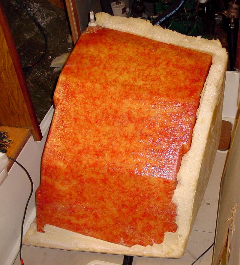
Looks like the foam was poured into a female mold with the icebox in place. The foam is about 3" thick and a bit inconsistent in density.
|
|
There is about a 3" gap between the foam and the hull on the outboard side and the bottom. More foam could easily be added once things are disassembled to
this point.
|
|
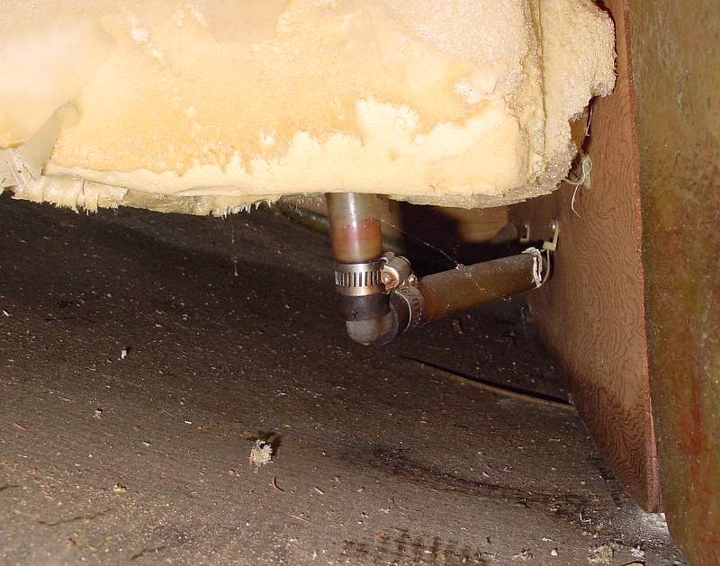
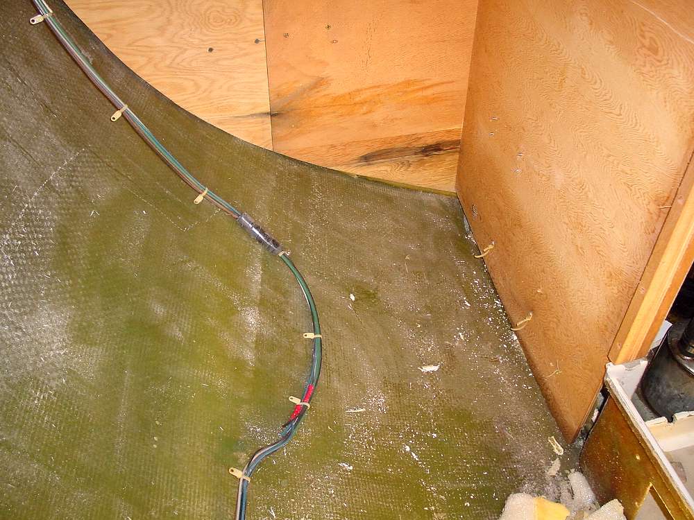
The icebox drains through a hose that runs into the engine compartment and up to a pump at the sink.
|

|
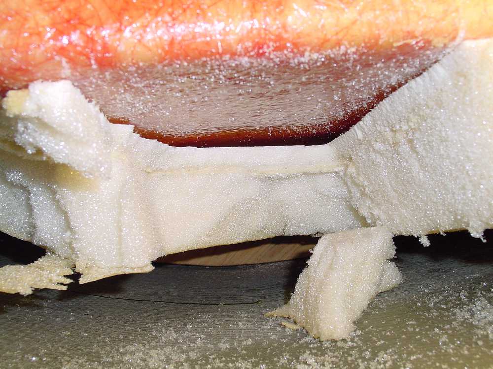
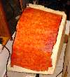
This is the forward face of the ice box with the foam insulation removed. The insulation came off by cutting it into blocks with a putty knife. The adhesion of the foam to the ice box was pretty weak which makes it easier to remove.
|
|
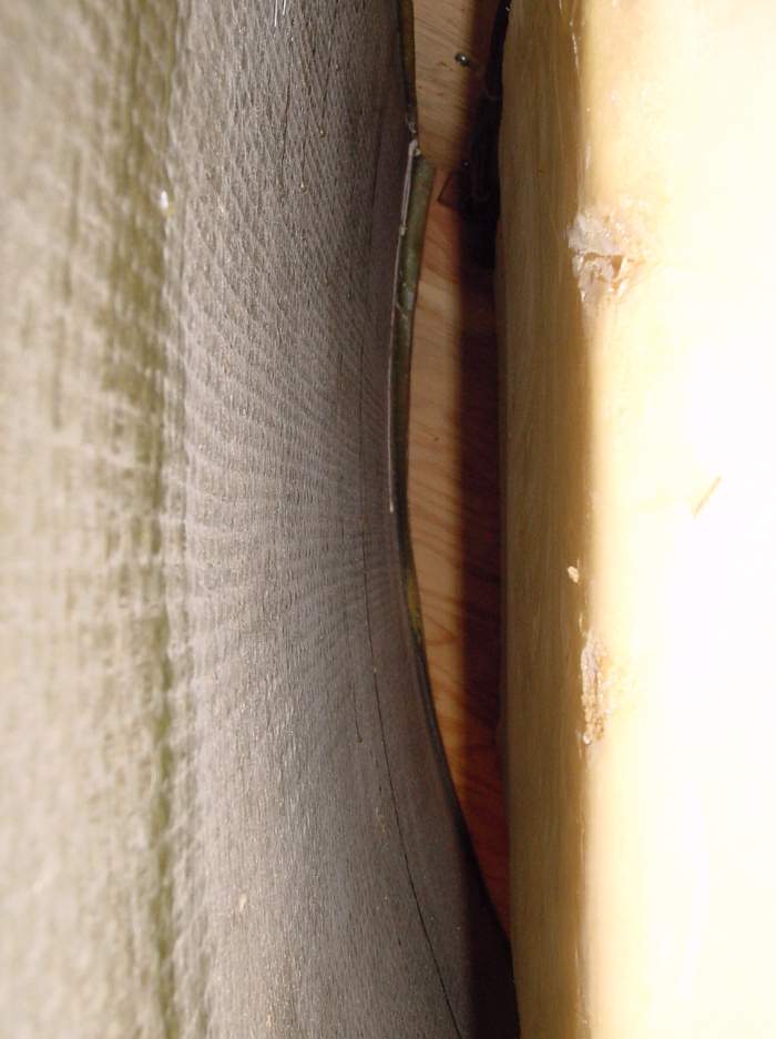
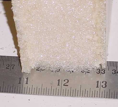
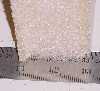
This is a cross section of the foam. It's about 2-1/4" thick and the density is a bit uneven. I don't know what the R value of this foam is as installed but I think it's probably not as good as some of the blue of pink stuff you get at the hardware store. There is room for improvement?
|

|
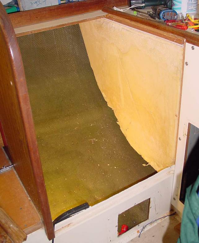
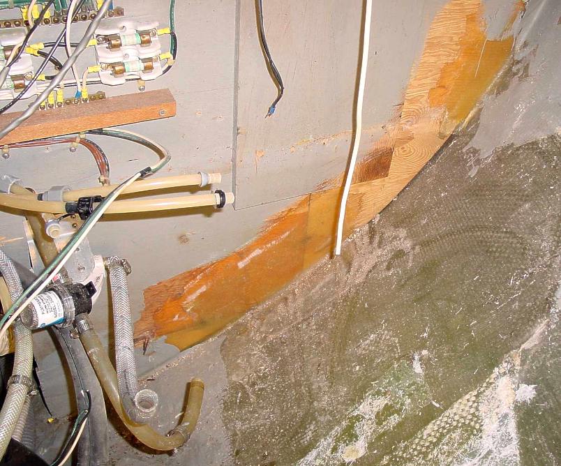
This shot sort of shows the extent of the tabbing on the longitudinal bulkhead between the engine compartment and the ice box. It is not very extensive and there is none on the ice box side.
|

|
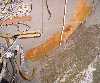
This shot shows the outboard side insulation partially removed. Thickness is about 3-1/4" which is better than the front face. But there was a large section where there was a gap of about 1/2" between the insulation and the ice box shell.
|

|
Most of the outboard insulation is removed here and you can see the forward face of the aft cabin bulkhead pretty well. Not that there is no tabbing of this bulkhead to the hull on the forward side. Note also that this bulkhead is made from two pieces of plywood spliced together.
|
|
This photo shows the aft side of the bulkhead. Note the somewhat light tabbing.
|
|
Here I have removed the teak frame that holds the sliding plexiglas doors for the galley locker and the face panel under the galley sink. I am going to have to remove the counter top to get the ice box shell out.
|
|
A drawing of the icebox with dimensions.
|

|
Getting the ice box out requires removal of the counter top. The ice box is held to the uderside of the counter top by screws that go down through the countertop into the ice box flange. The screw heads are covered by the formica. I peeled off the formica over the screws with my air hammer with a wide chissel (scraper) tip. This is a brutal tool that I also use to split tabbing. There are also screws along the back edge of the counter top under the forminca. Needless to say I'll be making a new counter top. That's probably easier than re-habbing the old one anyway.
|

|
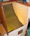
Nice shot of the galley area with the countertop removed and the ice box shell pulled out. My re-build plan will have the counter in two sections so the one over the engine can be removed for maintenance access.
|
|
The ice box shell had about two inches of insulation on all sides except the outboard side where there were three and room for maybe six.
|

|
This shot shows the forward side of the aft cabin bulkhead and the outboard side of the longitudinal bulkhead between the engine and icebox. Note that there is no tabbing connecting these bulkheads to the hull. That's because the galley was dropped in as an assembled unit and only the back side of this bulkhead was accessable for tabbing.
|