|
| Mast Step |
|
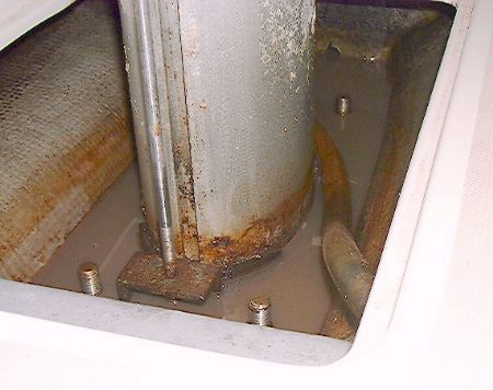
The OEM mast step on the 10M is made of steel. It sits in the bottom of the bilge and is in direct contact with the aluminum mast. Add a little salt water to this and you have a galvanic cell where the less noble metal will start giving up electrons. That's the aluminum in this case. Every 10M I have seen has this problem at the mast base. My solution is a new fiberglass mast step supported up out of the bilge on fiberglass floors (transverse beams). The new step sits 6-1/2 inches higher then the OEM. To maintain the proper rig geometry 6-1/2 inches would need to be cut off the mast. Some of the mast needs to be cut off to remove the pitted part that was damaged. I also chose to replace all of the standing rigging at the same time (it was original) so I cut only 1/2" of the mast. That raised the rig 6". My head sail is 6" taller but the main stays the same with the gooseneck going up 6" for some more headroom in the cockpit.
I spent many hours (hundreds?) working out the design of the new mast step on the computer with CAD software. I was helped imensly by Graham Bryan (10M #187, Jade) with his materials knowledge, engineering experience and machining skills. If you are interested in a simmilar refit for your mast step Graham and I can build you the parts. If you have an older 10M (before hull 101 or so) you might want to consider Grahams custom chainplate beam refit. See my chainplate page for details. |
|
|
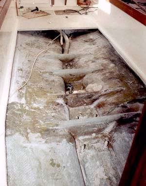
Removing Cabin Sole To gain access to the floors I cut out a large section of cabin sole. I cut it so that some supports can be made and it can be dropped back in. I will screw it down and there will be a seam but the access was necessary to do a proper job on the floors. It took me a day or two to finally work up the courage to cut out the sole. It's a balsa cored panel similar to the deck but with thinner fiberglass skins. The bottom may have been done with a chopper gun. The only way to get proper access to the floors was to cut out the sole. I used a higher end jig saw (Milwaukee) with good bi-metallic metal cutting blades to cut out the sole. I taped up the shoe of the saw so it wouldn't scratch the fiberglass pan and used the edge of the seat as a guide. This worked well on the starboard side bit I had problems on the port with the blade flexing and cutting at an angle. I should have left about 1/4" between the saw and the settee face and cut freehand. There are some cross braces spanning the floor and I would have just missed them with another 1/4" on the sides. I also made some measurements to be sure I could get the panel out through the companionway. At the forward end of the sole I had to cut the blade shorter so it wouldn't hit the inside if the hull. I cut it with my dremel and a cut-off wheel so it would reach about 2mm bast the bottom of the panel. |
   |
|
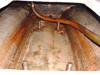
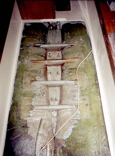
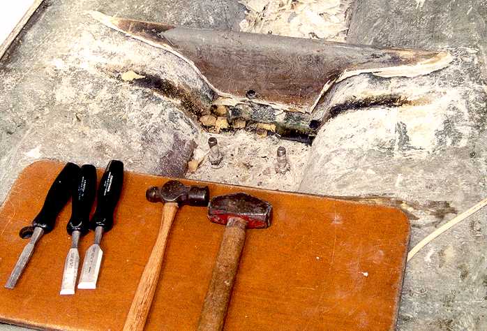
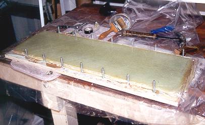
Floor Forms The aft floors are in original condition. They look funny in the photo above because of the gray paint. It was painted after the sole was in and they could only reach so far. When I put the sole back in it will be fastened with screws so it can be easily removed. I may re-do the other floors but for now I need to get the boat sailing again. I have seen another 10M where the aft floor (maybe the two aft floors) were separated from the hull because of a grounding. I added two new floors and replaced one of the OEM floors. I removed the forward most OEM floor because it's tabbing extended well into the area that I wanted to tab my new floors into. I could have added the new floor tabbing right over the OEM but the OEM tabbing was secondary bonding with polyester resin (the floors were tabbed in after the hull had cured). That is inferior to the epoxy secondary bonding the new floors would have so to get the best strength I needed to remove the old secondary bonding. It took me about three hours to chisel out the floor that I did remove. Next time I'll use an air chisel an it will take 30 minutes.
I decided to build the new floors in place rather then off the boat and then tab them in place. I think the overall construction is stronger with primary epoxy bonds throughout the structure. I made the forms from 1" thick foam insulation panels. This is a slightly denser foam the typical and I think it cuts and shapes more easily. I cut a rectangular piece and laid it in place spanning the bilge. I made marks to match the shape of the bilge using a level to keep the marks straight over the intended spot. I started at the lowest spot and transferred that dimension to the foam along the entire cross section. I cut the foam with a utility knife. I tried a hacksaw blade in a handle and had better control and a cleaner cut with the knife. I did the trimming with a 2" drum sander in my cordless drill. Slow speed gave excellent control. I used the sanding drum to round over the corners. I also made limber tubes (drains) from 1" PVC tubing (thin wall schedule 80). I cut off along one side so the bottom of the limber tube would be at the lowest point in the bilge for complete draining. I glued the forms to the hull with a mix of epoxy and 406 hardener. I should have used 410 fairing filler. The 406 is too hard to sand and the strength is not needed for the forms.
|
|
|
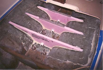
A level Surface for the Mast Step The mast step needs to sit on a level surface. That means the top of the floors need to be carefully made so they are the same height and level (crosswise). I adjusted the boat stands to get the cabin sole (the floor you stand on) level. On top of the foam forms I made small coffers (walls) from electrical tape to contain poured epoxy. I mixed up some epoxy with some 410 filler to a thick but pour-able consistency. I poured this into the coffers to get the same level in each. The advantage of this is if I got the levels to match each other gravity would see to making them level. Since the cabin sole was level they would match that. Level and parallel are foggy concepts on a boat and I think this is about the best you can expect. After the epoxy hardened I took off the tape and rounded off the corners. The tops of the forms were 3/8" lower then the height I wanted for the base of the mast step. |
|
|
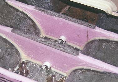
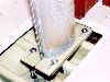
Glassing Over the Forms The floor lay-up and the tabbing to the hull was done as one continuous lay-up to create primary bonding throughout the floor structure. The bonding to the hull is secondary but with epoxy that's a lot stronger then the original polyester secondary floor bonding. I Started with 4" biaxial tape (West System #727) and laid that in around the corners where the forms meet the hull. I followed that with West System biaxial glass with .75 oz mat backing (West System #738). This glass wets out very nicely and is considerably stronger then woven roving. I cut pieces that went from the hull, around the corner at the base of the form, over the top of the form and part way down the other side. Then I did the same from the other side. This served to overlap the seams. My plan was to lay-up about 3/16", wait a couple hours and lay-up another 3/16" for a total lay-up thickness of 3/8" (a total of about 13 layers). But the lay-up process for the three floors took long enough that I didn't need this gap of time (I had been concerned about heat build up in the epoxy). So I basically kept cutting and wetting out pieces of glass for about 6 or 7 hours. It is fairly methodical work. I added pieces over the hull in between the floors to tie the whole thing together as a unit. The results looked pretty good and the tops of the floors were right where I wanted them. Note in the photo that I covered the keel bolts with PVC pipe and tape to keep epoxy off them. |

|
|
Mast Step Plates The mast step is made of two 7 x 14 x 1/2" thick fiberglass plates laminated from 17 layers of biaxial glass with .75oz backing in West System Epoxy (apr. .030 per layer). I did the lay-up in a jig made or 3/4" plywood. The top and bottom plywood plates bolted together to press the lay-up. Very little torque was needed on the bolts. It didn't take a lot to put a warp in the plywood. I used the 206 slow hardenera here and worked on a cool day to keep the lay-up from getting too hot (epoxy reaction produces heat). And I put a fan on the lay-up press as it set. This is very important. If the heat is not controled the epoxy can catch fire. Read and understand the West System literature. The top plate is slotted to slide for and aft on the bottom plate. 1/2" bolts hold it down. They go through the bottom plate into threaded holes in a stainless steel angle bracket that is bolted to the new floors. I did the lay-up of the plates as one large panel and cut them down on a table saw with a carbide blade. The cutting was pretty easy but the glass is very hard on the blades. The slots and holes were expertly made by Graham Bryan (10M #187, Jade) on a milling machine. |

|
|
|
Angle Brackets The mast step plates are connected to the floors by stainless steel angle brackets. The top of face of the brackets are threaded for the 5/16-18 bolts that hold the bottom plate down and 1/2-20 bolts that hold the top plate from sliding. I got the 2x2x1/4thick SS stock for the angle brackets from McMaster Carr. Graham Bryan did the machining. |
|
|
Mast Step Assembly The next step is to mount the SS angle brackets and install the step. Click below to see a sequence of photos showing the assembly. Mast Step Assembly |
|
West System web site- epoxy and fiberglass materials
McMaster Carr web site - hardware
I glued the foam forms in with epoxy/406 filler and did fillets in the corners. I should have used 410 fairing filler because it's way easier to sand and it only needs to be there to form the fiberglass over.
Same goes for the filler in the flat parts on top of the floors.
I should have cut the sole out with that extra 1/4" instead of using the settee front as a fence.
I should have triple checked the alignment of the new floors. The aft one is about 3/8 off on one side but that's not a structural issue, just wish I had paid better attention to that. The floors for the step are fine and that's what really counts.