 The cockpit floor of the Pearson 26 is balsa cored. There is an inner and outer fiberglass skin. The fiberglass skins are about 3/16-1/4" thick and the balsa core is about 3/4" thick. This type of construction has several advantages over a solid fiberglass lay-up. It is stiffer than the solid glass lay-up and provides insulation. The disadvantage is the construction technique requires more care from the builder to get it right. It is also more susceptible to damage from water leaks. When water gets into the core it degrades the bond between the core and the skin. It is therefore important to properly seal hardware mounting holes to insure that water doesn't find it's way into the core. You also need to re-enforce the deck area where the hardware is mounted, otherwise the core will be squished when the mounting bolts are tightened. This can lead to delamination. After removing the inner skin from mine I found the thickness varied quite a bit and the entire inner skin was made from fiberglass mat, there was no woven roving.
 The rudder tube on the boat is fiberglass and runs from the bottom to the cockpit sole. The tube is quite thick and husky and slopes forward about 16 degrees. The tube is glassed to the inside of the hull and the bottom of the cockpit floor. There was silicone sealant applied at the top of the rudder tube in the cockpit but it was not glassed in here ( Click for drawing). The balsa core is protected from water only by the sealant between the rudder tube and the cockpit floor. There is a plastic cap covering the top of the rudder tube in the cockpit. The cap is held down with screws that go into the balsa core. This is where water leaked into the core on my P26.
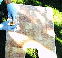
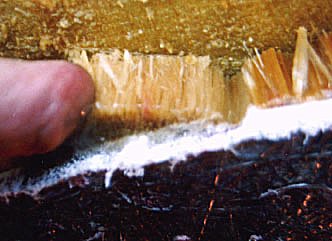 The core in my cockpit floor became wet and started to rot. I knew there was a small area of delamination from the hollow sound when I tapped on it. I also noticed that the floor just ahead of the rudder tube deformed when I stepped on it. I cut out a small section from below and the core was soaked. I kept cutting from below until I got to dry core. I cut out a bit less then 1/2 of the core and bottom skin. The photo here shows some wet core about a foot forward if the rudder tube. I am squeezing the water out with my finger.
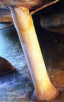
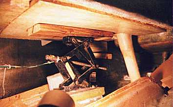
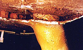 As I cut out the rotten core the source of the leak became readily apparent. The water had been coming in around the top of the rudder tube. When installed, a hole was cut through the cockpit floor. The rudder tube was glassed to the bottom skin of the cockpit floor but not to the upper skin. This was sealed with silicone. It seems that no other effort was made to seal the balsa core from water (Click for drawing). It had probably been leaking since the mid 80's. The photo here shows the top of the rudder tube, where it meets the cockpit floor, in a real life cut-away view. You can see the silicone bead protruding through the gap between the rudder tube and the upper skin of the cockpit floor. You can also see the screws that hold down the plastic cap over the top of the rudder tube in the cockpit - another leak source. They went right into the balsa.
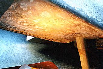 I cut the core out from below, removing the inner skin rather then the top surface of the cockpit floor. The floor surface was in excellent shape and I thought it would be better for cosmetics and water tightness to make the repair from below. On the P26 this is made easier since there is no inboard engine in the way. I cut the inner skin with a rotary bit in a dremel tool. This was very effective. I used my mini shop vac to suck up the dust from the cutting as I worked, holding the dremel and vacuum hose together. I also tried using a router to cut the inner skin but it was a lot messier and did not cut as fast as the dremel. Where the core was very wet I could cut large sections (4"x8") and they would almost fall off by themselves. As I worked forward and got to dryer core I cut smaller sections. Once at the dry core I could only cut sections about 2"x2" and had to drive a chisel into the balsa to break it off. I Cut about 3 to 7" past where I encountered dry core. 3" on the port side and 7" on stbd. I did this to be sure and get into dry core and get a straight edge (perpendicular to centerline) to join the repair panel to. The photo here shows the bottom of the floor with all the bad core and inner skin removed.
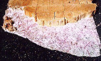 There were several patches (apr. 5x8") of inner skin that were not properly wet out with resin when the boat was built. The photo here shows the largest of the non-wet out patches that I found. The thickness of the glass work varied greatly from 2 to 5 mm. All the glass I removed was mat. I worked for about 1.5-2 hours at a time on the core removal. It took a total of about 6 hours. It could have been done faster in one long session.
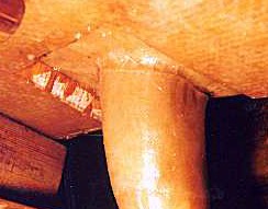
 I cut away the inner skin around the top of the rudder tube except on the aft side where it turned up to join the vertical aft face of the cockpit. I removed all of the rotten balsa core. Then I ground most the old tabbing off the rudder tube and started glassing the tube directly to the bottom of the upper skin of the cockpit floor with strips of 2" fiberglass tape and West System epoxy. The photo here shows the top of the rudder tube before I started applying the fiberglass tape. The drawing shows how I tabbed it to the upper skin of the original panel and to the repair panel. Compare this to the drawing of the OEM configuration.
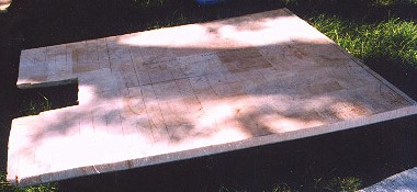 I decided to build the repair panel off the boat and glass it in as a unit. I chose to do this to have better control of the lay-up. I made a mold of sorts from plexiglass and waxed it with some car wax that I had handy. I laid down a sheet of woven roving and wet it out with West System epoxy. I worked with small batches at a time (3-4 pumps worth) and started in the center working to the edges. If you mix too much epoxy in a small container it can over heat (go exothermic as Gougeon puts it) from the reaction and set prematurely (I have seen it set cups on fire too). I used 206 slow hardener but could have used 205 since I was pouring it onto the cloth right away. I wet out the 1st sheet and added a second. The 2nd sheet of woven roving wet out easier then the first. The photo here shows the completed panel before installation. The cut out is to fit around the rudder tube. I cut it with a bevel to ease the transition of the tabbing I will put over it from the rudder tube.
 About 10 hours later I added 2 sheets of fiberglass mat wetting them out as with the woven roving except I used the 205 hardener (Both sessions were at about 72 degrees). I took the Baltek balsa core that I had already cut to size and wet out one side. I then placed it on the wet mat and covered the whole thing with a sheet of plywood and about 150lbs of weight. I also put a riser under the panel to induce some longitudinal bow. The floor is bowed this way and I wanted to reduce the amount of bending I would have to do when I put in the panel. I wanted to have to bend it a little to help distribute the clamping pressure. The photo here shows the new panel (on left) next to a piece of the OEM panel that I removed. The new lay-up is a bit thicker and you can see the layers of woven roving (the OEM is all mat). Also, there is a darker band in the OEM balsa where it may have wicked resin away from the mat. The Baltek in the new panel is resin impregnated to keep it from wicking.
 I took the new repair panel to the boat and trimmed it to fit. This process took a while. I test fit and trimmed over and over until I had a good fit. I cut of just a little at a time. I used a saber saw to cut. The fiberglass is brutal on the blades. I went through about 4 blades (wood cutting type) for maybe 20 feet worth of cutting.
Once I had the panel fit I cut a piece of fiberglass mat to fit the top side between the balsa and the underside of the upper skin on the boat. The mat provided a way to get a lot of epoxy on the mating surface and fill in the variations of the surface. The glass/resin ratio was probably not ideal but I think the contact was better and I figured poor ratio with good contact is better then good ratio with poor contact. I wet out the mat while a helper wet out the underside of the mating surface on the boat. It took about 20 pumps of epoxy to wet out the mat and 5 to wet out the mating surface on the boat. It was important to have a helper here. I used the slow harder (206) which gives 20-25 minutes of working time. I took about 20 minutes wetting out the mat. I needed the rest of the time to place the panel on the boat. It worked out very well. The photo here shows the layer of mat on top of the panel being wet-out with epoxy.
 I also made a stand for a scissor jack and a curved board to give better contact with the repair panel. I had the jack all set up and slid the panel right in. I cranked the jack up and checked the fit one last time. Every thing looked good and some epoxy was oozing out the edges. I jacked it up so the deck was pressed up about 3/8" from normal. I left the jack in place overnight. The photo here shows the jack in place holding up the panel.
After about 24 hours I removed the jack. The repaired section was very stiff even though it had not yet been tabbed in. It appears to deflect a bit less under load then the OEM section at the front of the cockpit - It feels stiffer under foot. The new section is about 10%-15% thicker then the OEM section. That should make it about 30%-45% stiffer according to my engineer friend. The layers of woven roving probably help too, the OEM lay-up was all mat.
 I made a cut-out in the panel to go around the rudder tube. I also sanded away some of the balsa surface on the top of the panel to fit over the tabbing I had already done between the rudder tube and underside of the upper skin of the cockpit floor. I cut the panel back about 2 inches from the rudder tube and beveled the edges so the tabbing would not have to make a 90 degree turn.
-DHP